Data Structure and Dataflow Maps - Structural Metadata Management
Overview
Dataflow Maps are almost identical to a Data Structure Map, except that the mapping is performed between two Dataflows. The remainder of this section describes Data Structure Maps, however all statements hold true for a Dataflow map. Data Structure Maps are used to map Components (Dimensions and Attributes) from one Data Structure to another. This relationship between two Data Structures can be used to map data queries, or datasets from the source Data Structure to the target Data Structure.


Figure 1 showing the view of a Data Structure Map
Data Structure Map Wizard
The Data Structure Map Wizard includes the first generic step for information.
The second step of the wizard is to pick a source and target Data Structure; this defines which two Data Structures will be mapped. To add or modify a source or target, click in the input field to open a list of available structures.

Figure 2 showing the selected source and target Data Structures
The third step is used to define how the Components of the source Data Structure map to the Components of the target Data Structure. The Source table on the left of the page shows the available Components of the source Data Structure. Selecting a source will update the Target table in the middle of the page, which shows all currently mapped targets. The Available table on the right of the page shows all the Components of the target Data Structure which are not yet mapped to the selected Source. Components can be moved from Available to Target and vice versa by selecting the component in the target or available table and clicking the left or right arrow.

Figure 3 showing step 3 of the Data Structure Map Wizard
The last step of the wizard provides a mechanism to define, for each mapped Component, how their representation is mapped. For example if two Reference Area Components are being mapped, with the source Reference Area using an ISO 2 character country Codelist and the target using the ISO 3 character Country Codelist, this step of the wizard provides the mechanism to define the mapping used between each Code in the source and target Reference Area Codelists.

Figure 4 showing step 4 of the Data Structure Map Wizard
The above image shows the Component Maps on the left of the page, as defined in step 3 of the wizard. Each mapped Component can have a Representation Map defined. A Representation Map falls into one of the following three categories:
- Implicit – this type of mapping states that the source and targets values will be the same and therefore there is no need explicitly define the mapping. For example if the content is textual, or if the components use the same Codelist, or the source and target Codelists share the same Code Ids then implicit mapping can be used.
- Explicit (Value Map) – this type of mapping is ‘inlne’ and stored as part of this Data Structure Map. A value map is imported using CSV, of source to target (as shown below). A Value Map can be used to map any text content and therefore does not have to be a valid Id ($, £, % can all be mapped for example).
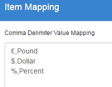
- Figure 5 Creating a Value Map from CSV
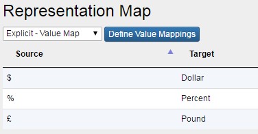
- Figure 6 The resulting Value Map in a Table
- Explicit (Codelist Map) – this type of mapping references an existing Codelist Map, which is created and maintained separately of this Data Structure Map. This option is only available if there is a Codelist Map defined for the Agency which maps between the source and target Codelist as used by the source and target Components that are being mapped. Codelist Maps are discussed in the next section of this document.
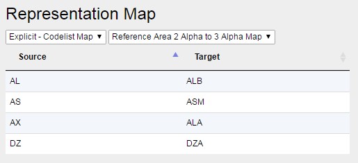
- Figure 7 showing the use of an Explicit Mapping to define how the values between two Components map


